Propeller Wake Visualization
Experimental attempts at visualizing the wakes of small UAV propellers.
TL;DR: I spent a long time trying to visualize the wake of a very small propeller. It was mildly successful!
Very early on in my Ph.D., I worked on a project involving extremely small UAVs. The end goal was to build a swarm of tiny UAVs that could construct complex 3D formations in compact spaces–think drone shows but scaled down to fit in your room.
Unfortunately all (rotary-wing) UAVs emit a wake of relatively high speed and turbulent air as a byproduct of generating thrust. This wake can extend many propeller diameters below the UAV. This becomes a big problem when we start thinking about miniaturizing drone shows because
- the UAVs have to operate much closer to each other relative to the size of each wake; and
- smaller UAVs are not particularly robust to any appreciable wind gusts. In contrast, full size outdoor drone shows leverage the fact that the drones can be spaced much further apart and still make a coherent formation from the appropriate distance. Not to mention these larger drones can actually handle moderate wind disturbances without much of an issue.
So, I decided to try and measure the wakes from our tiny propellers to see if we could fit an adequate model of the downwash for downstream planning tasks. This proved to be a much bigger challenge than I had initially thought.
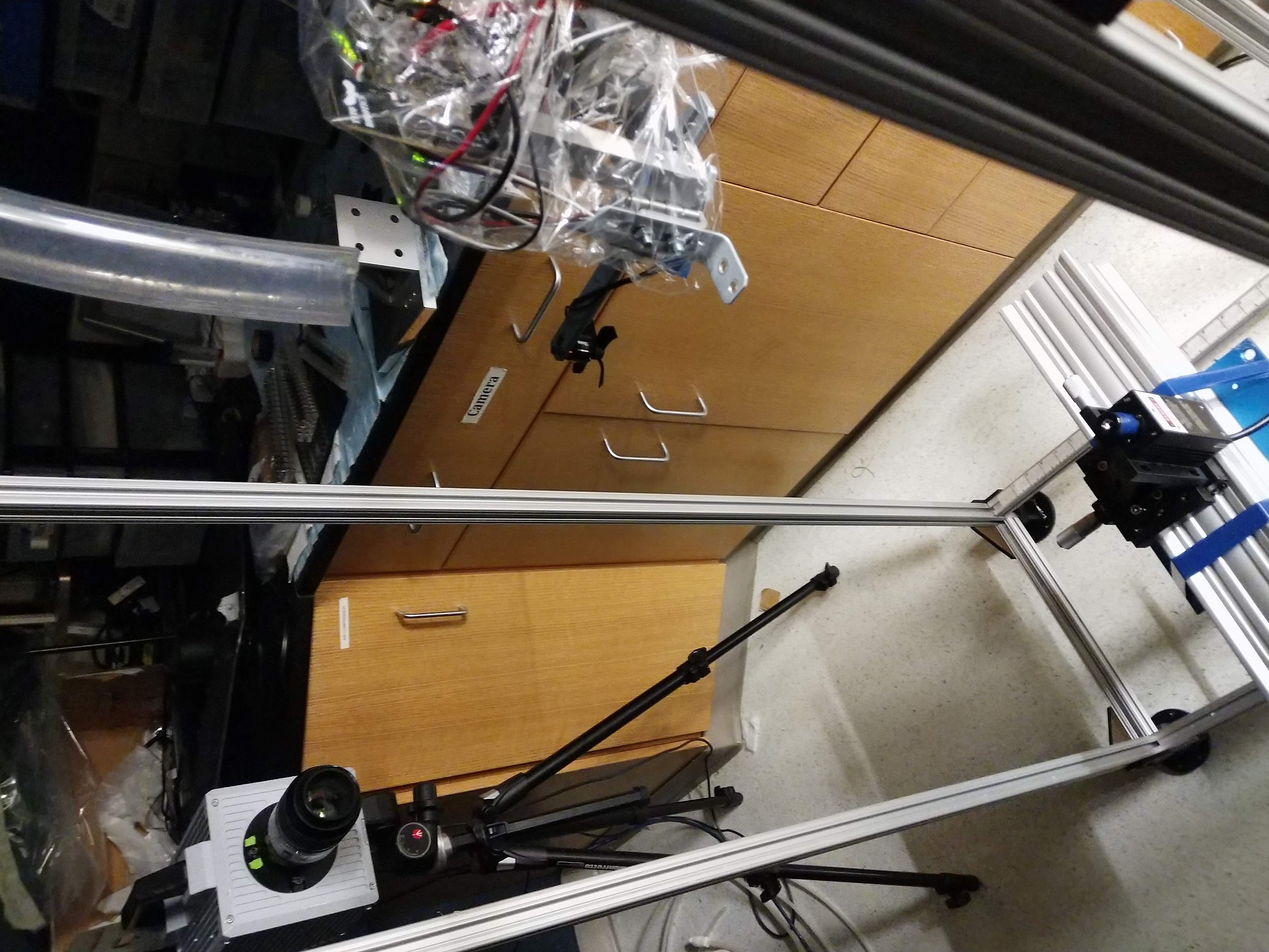
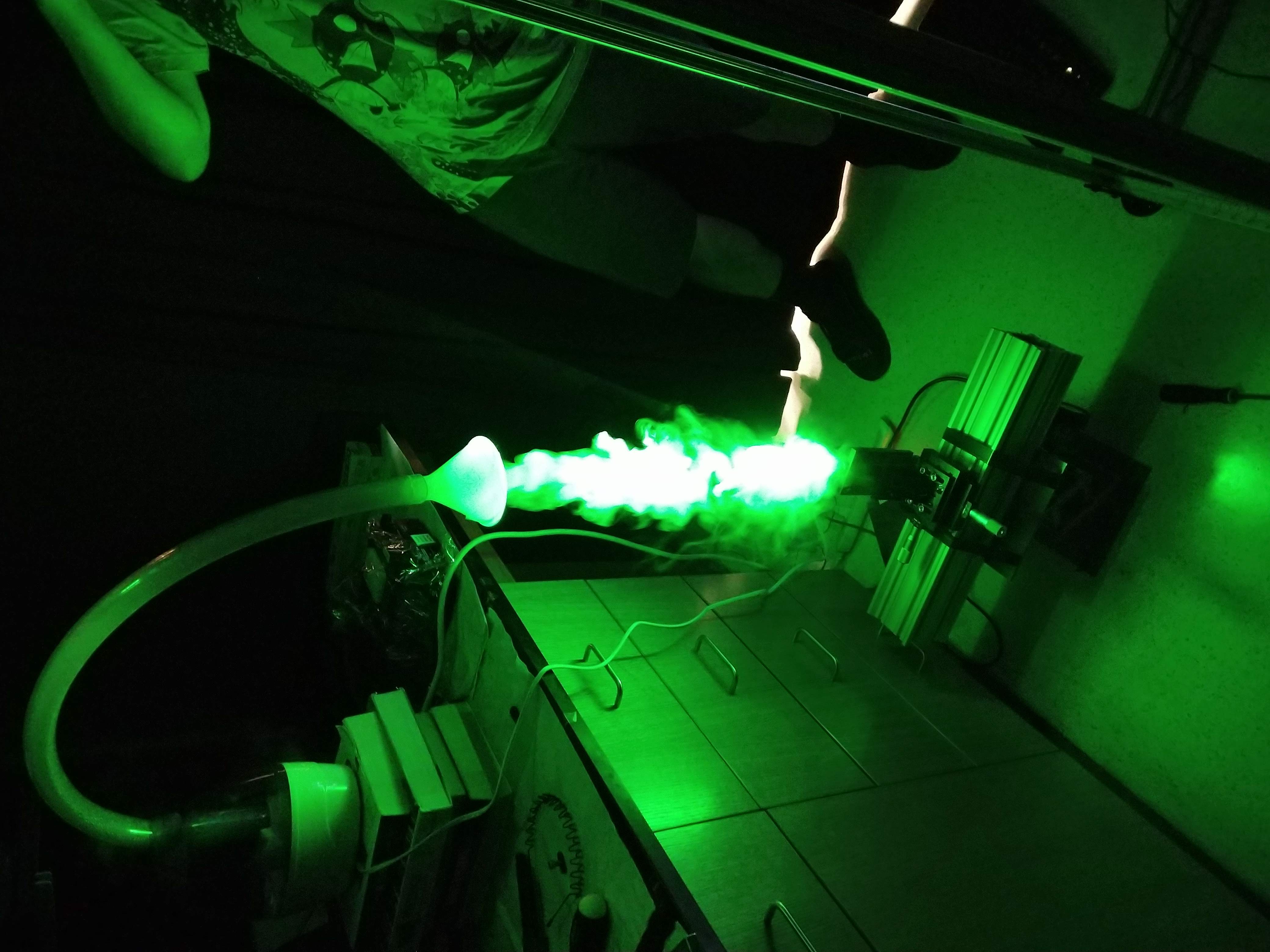
I teamed up with two former Ph.D. students from Paulo Arratia’s fluid dynamics group, Ran and Bryan, to hack together a basic particle image velocimetry (PIV) setup that included a laser, high speed camera, and an off-the-shelf humidifier for flow seeding.
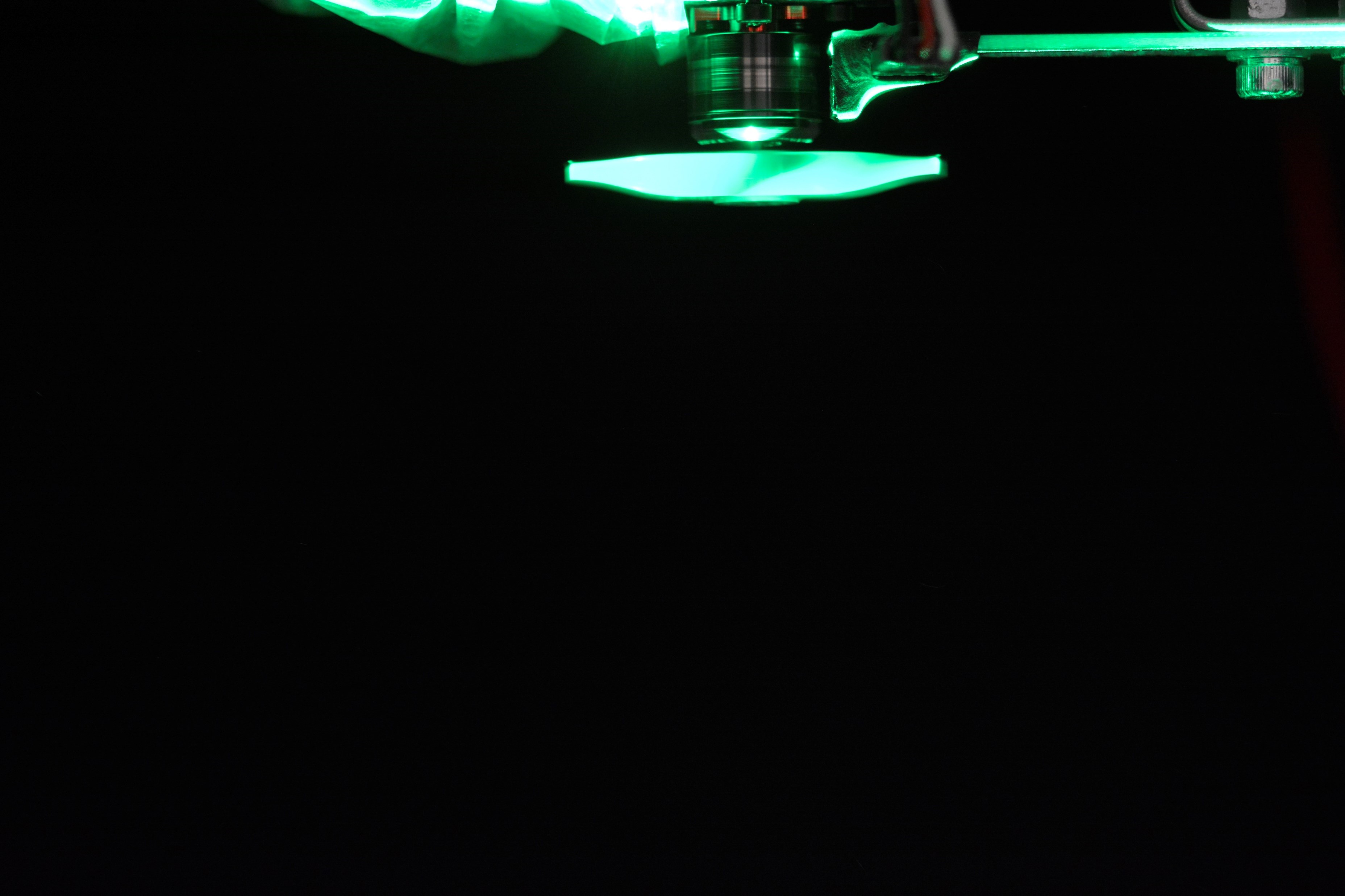
From this setup we were able to obtain this slow motion video of water vapor particles in the wake of the propeller.
It was pretty cool to see this visualization for the first time! Most of the vapor collects near the hub where low speed vortices shed off at the root connection. It also gives a good impression of how turbulent the wake from these small propellers are. You’ll also notice a flashing that occurs on the left side of the screen. This is caused by the oncoming propeller blade crossing the laser plane and reflecting light back towards the camera. We later tried to fix this by spray painting the propeller matte black, and it sort of helped!
Here is a wake visualization for the same propeller operating at 15,000 rpm.
While the visualization certainly looks cool, we weren’t really able to capture much velocimetry data from this. At higher speeds, the water vapor was too diffuse and our laser was too weak to capture the individual vapor particles necessary for PIV. Nevetheless, we did manage to get velocimetry data at 5,000 rpm and 7,500 rpm.
The animated velocimetry data further demonstrates how turbulent the wake flow field is. It seems that on average the wakes were between 1 and 2 m/s on average. Keep in mind though that typically these propellers operate between 15-20,000 rpm.
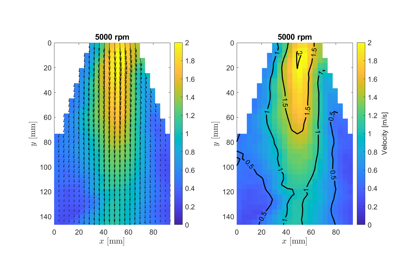
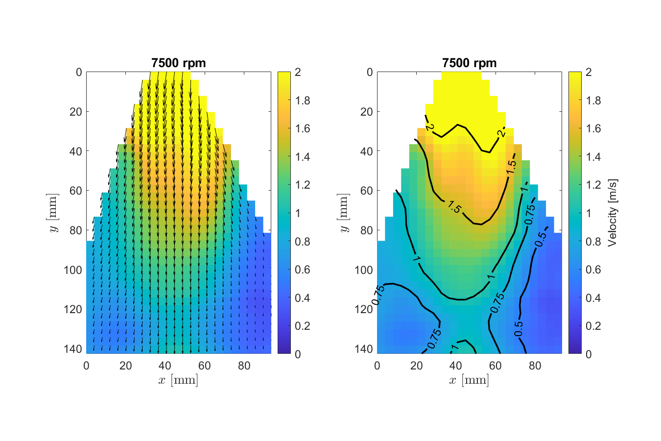
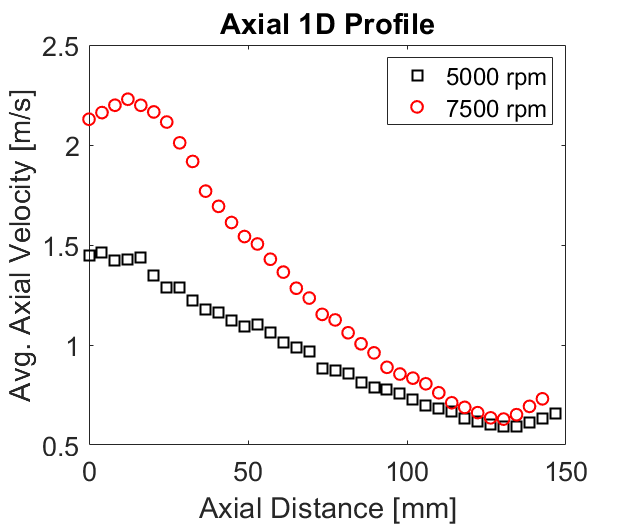
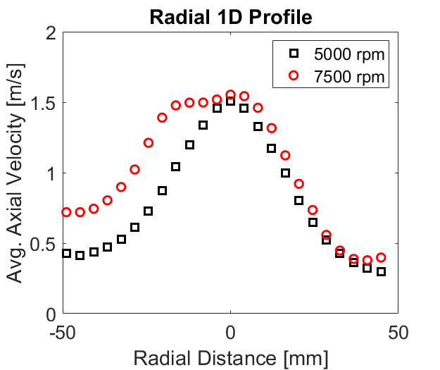
We knew from flight testing that the propellers were spinning at upwards of 20,000 rpm in hover, but due to hardware limitations we couldn’t visualize the wakes at that speed, much less extract any useful velocimetry data. So ultimately, we decided to pivot. Nevertheless, I am extremely satisfied with the visualizations we were able to come up with, especially given the budget and resources available to us at the time!
Of course, huge credit goes to Ran and Bryan for helping design the experimental setup and run the velocimetry calculations on the footage we captured.